- Home
- In Our Community
- Construction Projects
- Philips Highway (US-1) Greenland Energy Center to Race Track Road Electric Reliability Project
Philips Highway (US-1) Greenland Energy Center to Race Track Road Electric Reliability Project

Project Objective
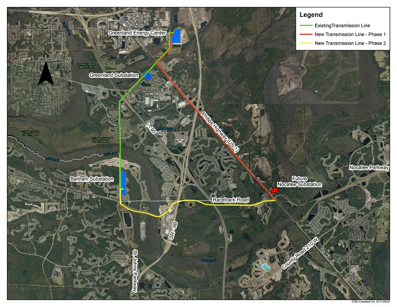
JEA has completed construction on an important infrastructure project to install new electric transmission poles and power lines along both Philips Highway (US-1) and Race Track Road. This electric reliability project connects JEA’s existing Bartram Electric Substation (4513 Race Track Road) to the Greenland Energy Center (6850 Energy Center Drive) and the future Nocatee Electric Substation (14987 Philips Highway).
JEA completed the installation of the poles on US-1. On June 22, 2020, we began Phase 2 of the project along Racetrack Road.
JEA engineers design transmission and distribution voltage systems so that JEA can supply power from alternate sources or substations in the event an outage occurs. This alternate-source design helps to minimize electric outages and outage durations for our customers.
The project includes two new, overhead electric circuits will create a critical redundancy in our system, providing backup/fail-safe power when needed most. The end-result is more reliable energy for our customers. This project also will allow for continued growth of the Jacksonville community in the southeast region of JEA’s electric service territory.
Traffic Alert Updates
Daily Single Lane Closures on Philips Highway
For the safety of our crews and the general public, we were required to temporarily close the southbound westerly lane on Philips Highway from the Greenland Energy Center (6850 Energy Center Drive) to the future Nocatee Electric Substation (14987 Philips Highway), from February 22nd through April 30th, Monday through Friday, and on April 10th and April 17th (Saturdays) between the hours of 9:00 a.m. and 3:30 p.m. each day. There were no closures on Easter, Sunday, April 4th. These temporary lane closures were necessary for our contractor to complete the installation of the conductors for the Nocatee substation. Please see the work area map below.
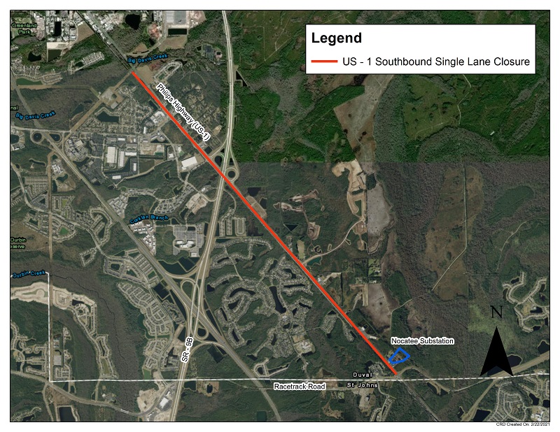
Traffic Pacing on I-95
To allow crews to safely install lines across Philips Highway at SR-9B The Florida Highway Patrol reduced speeds to 20 mph on SR-9B.This traffic pacing operation took place on March 14th between the hours of 4:00 a.m. and 5:00 a.m.
Project Route Selection
Learn more about how JEA Engineers chose the current route for the project.
Project Scope
This estimated $15 million project was divided into two different design and construction phases to meet the final JEA requested in-service date of April 2021*.
• Phase 1 included work along Philips Highway (US-1) from Greenland Energy Center to Race Track Road.
• Phase 2 included work along Philips Highway (US-1) from Greenland Energy Center to Race Track Road and on Race Track Road from Philips Highway (US-1) to the Bartram Electric Substation.
A contractor working for JEA (C and C Power Line) installed a new overhead 230 kV, 3-phase electric circuit starting at JEA’s Greenland Energy Center and ending at the Bartram Electric Substation (see below map). The construction included the installation of 103 power poles, 150,000 feet of transmission conductor, and 50,000 feet of shield wire, which is used for lightning protection. The overall transmission line is approximately 9 miles long.
Project Map Area Maps

Tentative Project Schedule
- Town Meeting #1 - February 7, 2019
- Town Meeting #2 - March 28, 2019
- Final Design and Survey Work (Phase 1) - August 2018
- Phase 1 Construction Start - May 2019
- Phase 1 Construction Completion - December 2020**
- Final Design and Survey Work (Phase 2) - January 2020*
- Phase 2 Construction Start - June 22, 2020*
- Phase 2 Construction Completion - April 2021*
*All dates are highly subject to change
** Note: C&C Powerline was awarded both phases of this project. As a result, instead of having to complete this project in separate "phases" the contractor can work in both sections simultaneously. Installation of the poles was first be completed in both phases, followed by the pulling of new electrical lines. Phase 1 and Phase 2 construction completion now both reflect the anticipated completion date of December 2020.
Public Meetings
March 28, 2019, 6:30 p.m. at Bartram Springs Elementary School
The second informational public meeting for this project was held on March 28, 2019 and began at 6:30 p.m. at the Bartram Springs Elementary School cafetorium located at 14799 Bartram Springs Way, Jacksonville, FL 32258.
This meeting utilized an open house format where customers within the entire project route were encouraged to attend any time between the hours of 6:30 p.m. and 8:00 p.m. to discuss the project and get answers to questions directly from our project team. Invitations were mailed via U.S.P.S. and emailed to the addresses on file for JEA account holders within the project boundaries.
February 7, 2019, 6:00 p.m. at Bartram Springs Elementary School
The first informational public meeting was held on February 7, 2019 at Bartram Springs Elementary School.
View the email sent on both January 24, 2019 and February 7, 2019.
If you are interested in receiving periodic updates and future invitations to public meetings regarding this project, please make sure to update your JEA account information or send us an email at projectoutreach@jea.com to request to be added to our project mailing list.
Construction Conditions
There was heavy construction equipment located along the transmission line path. Most of the equipment and work took place near each pole installation site with maintenance of traffic (MOT) set up near each site. In the early stages of construction, there were lumber trucks entering and leaving Philips Highway (US-1) to haul away lumber and vegetation removed between the highway and the railroad. Similar activities occurred along Race Track Road near 9B.
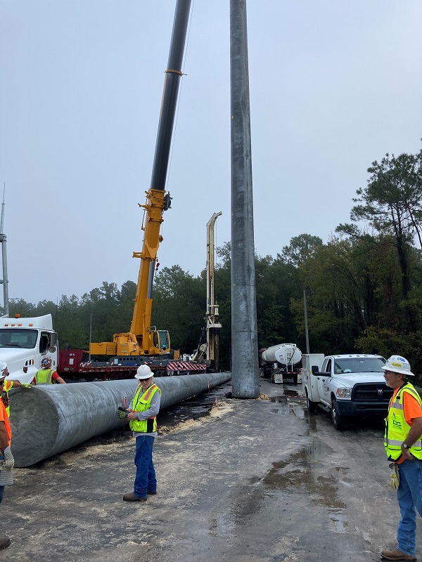
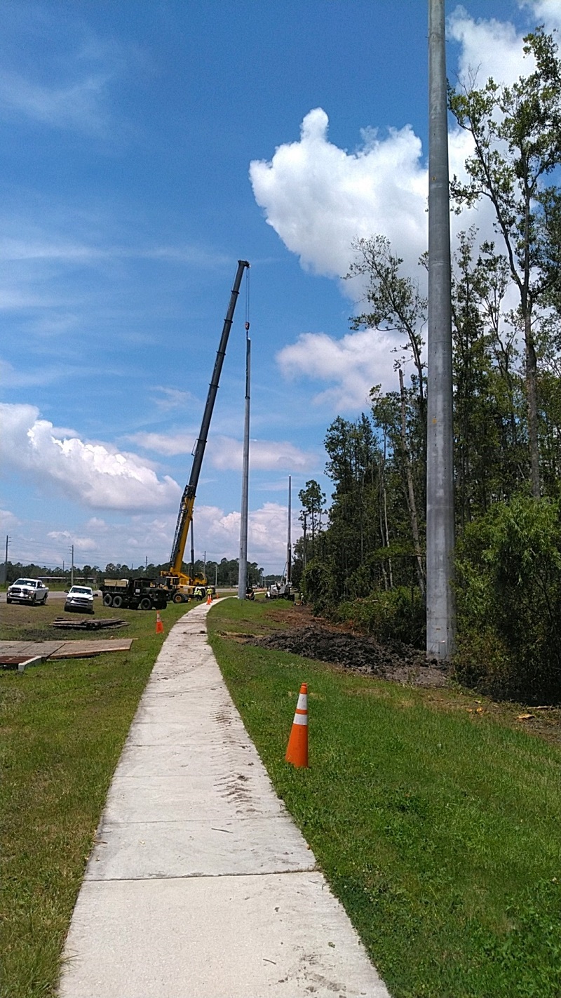
During the pole installations, there were large escorted trucks entering and leaving both Philips Highway and Race Track Road to drop off transmission poles at each installation site. A crane was also be positioned at each pole installation location. During the conductor installation, dollies (a type of pulley) were installed on each insulator to allow for wire to be strung from one pole to the next. Bucket trucks were positioned at poles being installed. Sagging and tensioning equipment was used to pull conductors/wires into place.
Two different installation methods were used, depending on the type of pole being installed:
1. For concrete poles: An auger was used to drill a hole of a specified diameter and depth. The hole was then be kept open by use of drilling mud and a steel can if necessary. A crane was then be used to lift each pole and directly embed the pole into the hole based on the designed embedment depth. The hole was then be backfilled with large (#57) gray stone.
2. For steel poles: Steel caissons (pilings) were used as foundations. The steel caissons were vibrated into the ground with the use of a vibratory hammer. An auger was also used to aid in the caisson installation. The poles were then be bolted onto the top flange of the caissons.
The construction laydown or staging area was primarily located on JEA property at the Greenland Energy Center (6850 Energy Center Drive) and electric easement near the Bartram Substation (4513 Race Track Road). The contractor also staged materials along right of way as they worked their way through the project.
The below video shows poles being installed by Patton Soccer Park off Hodges Boulevard. Similar size poles and lines were installed along US-1 from Highway 9B to Race Track Road using a similar installation process.
Tree Removal and Vegetation Management
JEA was required to remove and clear trees and vegetation along the project route. The tree and vegetation removal along Philips Highway and occurred at the beginning of the project. There was additional tree and vegetation removal along Race Track Road during Phase 2 of the project. These removals were required to install the new power lines and to safely operate the transmission lines once they were energized.
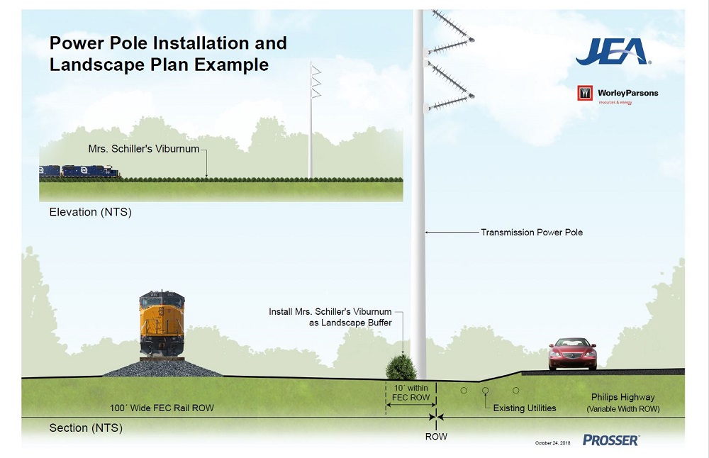
JEA did not remove any vegetation or trees between the FEC Railroad and the Bartram Springs Community. It may be possible to be able to see the top of the transmission lines from certain vantage points.
View an example of the landscape plan below.
Contractor's Normal Work Schedule
In March and April 2021, the contractor will work daily, including weekends. All work will take place during daylight hours (between 7:00 a.m. and 6:00 p.m.). The contractor may have been required to work during the evening hours when working near the signalized traffic intersections on Philips Highway (US-1).
Lane closures on Philips Highway were dictated by the Florida Department of Transportation (FDOT). JEA worked with the contractor to avoid lane closures during high traffic periods on both Philips Highway and Race Track Road.
Frequently Asked Questions (FAQ)
1. Why does JEA need to build a new electric circuit (909) along Philips Highway (US-1) from the Greenland Energy Center (GEC) to Race Track Road?
JEA must be prepared to meet the electrical needs of all customers (current and future) in one of the fastest growing areas of Jacksonville and in the State of Florida.
The overall purpose of the new transmission line is to serve the future Nocatee substation, which is needed to serve the growing communities within the area and to reinforce the reliability of the transmission system in this area of JEA’s service territory.
The future Nocatee substation will provide reliable and resilient electric services to current and future customers in this growing part of JEA electric service territory including all the existing developments along Race Track Road.
In order to reliably serve the increasing JEA electric load in the Bartram/Nocatee area, a future Nocatee substation will be constructed at the northeast corner of Race Track Road and US-1/Philips Highway by the fall of 2020. This new circuit (909) will be interconnected to serve the future Nocatee substation.
JEA engineers design transmission and distribution voltage systems so that JEA can supply power from alternate sources or substations in the event an outage occurs. This alternate source design helps to minimize electric outages and outage durations for JEA customers.
The northern part of circuit (909) will provide power to the future Nocatee substation from the Greenland Energy Center (GEC) substation and the western part of the circuit (909) will provide power from the Bartram substation.
At least two (2) diverse (different) transmission sources are needed to reliably serve JEA's 26.4kV substations such as Greenland, Bartram, the future Nocatee, as well as all other 26.4kV substations located throughout our service territory. This creates much better electric reliability and redundancy in the system.
In the event of a contingency (such as a natural disaster, terrorist attack, industrial accident or mechanical failure), the two circuits must be separated so that if one fails, the other remains in service.
Additionally, there are other new developments planned in this area, such as the Beachwalk, which will soon add more homes, schools, retail and commercial space. JEA must be ready to serve the growing population of this area.
2. How will this electric reliability project benefit the Nocatee community and and the surrounding area?
JEA designs our distribution system to be able to continue to supply our customers even after a single contingency event (such as lightning burning down a main line conductor segment or vehicle hitting and damaging JEA pad mounted equipment). For the Nocatee area, distribution lines that serve the various neighborhoods within Nocatee get energized from a JEA electric substation over 5 miles away. If anything unexpected occurs, then power may go out until JEA can either quickly repair the issue or reconnect the neighborhood to another backup JEA circuit until the final repairs are complete.
The future Nocatee substation will allow these distribution lines within Nocatee area to be energized from this new, closer JEA substation thus reducing the chance of unplanned events effecting neighborhoods. Essentially, the shorter the circuit, the less risk of electric outages. In addition, the new substation will allow JEA to split existing circuits in two and thereby reduce the load on each circuit. This allows these circuits to be available to serve as backup circuits themselves. JEA designs our distribution system to be able to continue to supply our customers even after a single contingency event (such as lightning burning down a main line conductor segment or vehicle hitting and damaging JEA equipment). By having backup circuits available, we can restore power more quickly after something unplanned occurs.
3. How will this electric reliability project benefit the Julington Creek community and the surrounding area?
JEA designs our distribution system to be able to continue to supply our customers even after a single contingency event (such as lightning burning down a main line conductor segment or vehicle hitting and damaging JEA pad mounted equipment). For the Julington Creek area, the distribution lines that serve the various neighborhoods get energized from the existing JEA Bartram electric substation.
The future Nocatee substation will allow these existing distribution lines energized from this existing substation and the corresponding substation transformers to be offloaded by serving some existing and new customers from the new Nocatee substation instead of the Bartram substation. This allows these existing circuits in the area and substation transformers to have additional spare capacity available to serve as backup circuits. By having additional new capacity available from the Nocatee substation, we can energize these existing distribution circuits in various ways depending on the unplanned outage event location. By having backup circuits and additional substation transformation available with spare capacity, we can restore power more quickly after something unplanned occurs.
4. How will this electric reliability project benefit the Bartram Springs community and the surrounding area?
The Bartram Springs subdivision and surrounding areas are currently served by JEA’s Bartram Electric substation located in the JEA electric easement near the intersection of Race Track Road and St. Johns Parkway. This substation continues to pick up the new electric load required to serve all the new developments and businesses located in this fast growing area of southeast Jacksonville.
As part of the overall electric service improvements planned, the new Nocatee substation, which will be located near the intersection of US-1 and Racetrack Road, will provide direct relief to the Bartram Electric Substation by serving the areas closest to the Nocatee substation which include the Bartram Springs subdivision. The new Nocatee substation will provide a robust source of power that is much closer to the Bartram Springs subdivision than either the Greenland or Bartram substations.
The Nocatee substation will be fed directly by the new 230 kV transmission lines that will be installed along Philips Highway (US-1) and Racetrack Road from Greenland Energy Center. This will directly enhance the electric service in the Bartram Springs subdivision. Once the overall project is completed, the Bartram Springs subdivision will be served by multiple electric substations (Nocatee and Bartram) which will also increase electric reliability, allow for future growth and assist during the restoration of electric service during contingency outages such as storm events or maintenance.
5. How was the project route selected?
The JEA Real Estate and Transmission Engineering teams evaluated multiple route options, including the east and west side of Philips Highway (US-1). The evaluation criteria included present and future development impact, economic impact, environmental impact and development impact
6. Why was the current project route selected?
The west side of Philips Highway (US-1) will be better for overall constructability and long-term maintenance. Constructing the power line on the east side of US-1 would have been pushed eastward, out of the ROW, due to utility crowding in the ROW. This would have necessitated directly taking property from owners on the east side of US-1.
There is a good possibility that the Florida Department of transportation could want to widen US-1 at some point in the future which would require JEA to relocate poles. The existing smaller distribution lines on the east side would need to be underbuilt which contributes to design complexity and complicates future operations and maintenance.
Evaluation of the routes did not indicate property values would be negatively impacted on the west side of Philips Highway (US-1), adjacent a railroad and an arterial highway. Additionally, cost for property acquisition on the east side of the road would be exponentially more. If even one owner had contested the taking, and forced a condemnation process, the presence of a viable alternative on the western side of US-1 would have resulted in the failure of the condemnation process.
7. Can the current project route be changed or altered?
A better route exists at the current location of proposed power line. Some of these reasons include:
- Cost: It would be a significant expense to alter the path of the line. The entire line south of 9B would have to be redesigned, new easements would need to be acquired and purchased, additional tree mitigation would be required, new permits would have to be issued, new poles would have to be ordered. There would be substantial construction delay(s) and change orders to contracts as a result of the change in scope.
- Conflicts: There are multiple underground conflicts along the eastern route with existing utilities. Utilities would need to be relocated.
- Maintenance: There is an existing overhead distribution circuit currently located on the north-east side of the highway. Maintenance on this distribution line would become more difficult as outages on the overhead transmission line would be required to change out poles and perform general maintenance. Building a transmission line over an existing distribution line is common practice, however, when an alternate route exists, it is not logical to create a maintenance issue.
- Easements: Easements would need to be purchased for the entire length of the line that is to be relocated. The easements would be needed for conductor “blow-out”, the conductor swing that occurs when wires are displaced by wind.
- Road Widening: If FDOT wants to widen Philips Highway, and JEA’s poles are in conflict, JEA would be forced to relocate the poles outside the FDOT right-of-way. At the current location, the only authority that could force JEA to relocate is FEC.
8. Why doesn’t JEA underground (bury) these transmission lines?
Some of the factors for not undergrounding (burying) the transmission lines involve: Industry best practices, cost, and constructability.
- Industry Best Practices: Burying large 230kV transmission lines such as the ones installed during this project are not a common practice in the electric industry. Overhead electric lines are easier to detect issues and repair, and as a result, provide faster restoration times. Underground lines are more difficult to maintain and can be subject to damage due to ground movement or water intrusion.
- Cost: Burying power lines is very expensive. The overall cost of the proposed overhead transmission line is currently about $14 million. Alternatively, an underground transmission line in the same area, same voltage, and of the same length is estimated to cost upwards of $100 million. This estimate does not take into account any additional easements that may or may not be required to build an underground transmission line, obstructions and/or unforeseen conditions.
- Constructability: While lower voltage distribution lines that connect to homes and businesses can be buried directly in the ground with less invasive construction, underground transmission lines require substantial underground infrastructure and many design considerations. Obstructions such as existing utilities, major roadways, overpasses, railroads, soil conditions and topography can have major impacts to engineering and construction. A transmission line similar to the one required for this project would typically be trenched, not directionally drilled. Only small segments where it would be impractical to trench would drilling be considered. Directional drilling of the transmission line would also not be allowed inside the FEC railroad right-of-way.
9. Can you provide detailed information regarding the new transmission poles?
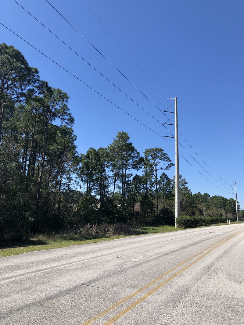
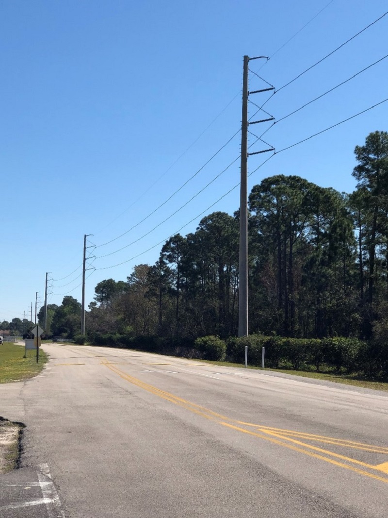
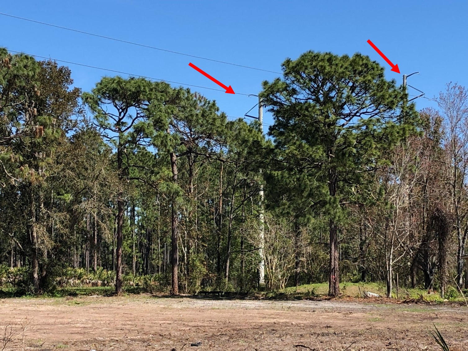
The poles for this project will range in height between 102 feet to 126.5 feet above grade, with most of the poles around 103 feet above grade. Taller poles will be required at the intersections of Old St. Augustine Road, Interstates 9B/95, and Durbin Creek to allow for proper clearances. They will be installed approximately (18) feet from the edge of pavement and will either be gray spun concrete or silver galvanized steel. Similar size poles can be found along the Florida Power & Light (FPL) transmission corridor along US-1 south off Race Track Road.
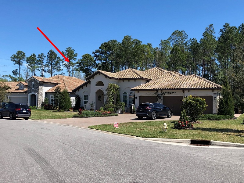
The structures in the photo below are approximately 103 feet tall, 230 kV concrete spun poles and transmission lines located at Patton Soccer Park off Hodges Boulevard and in the Tamaya community. Similar size poles and lines will be installed along US-1 from Highway 9B to Race Track Road.
The voltage, type of structure, number of structures, number of circuits and load (at the time) vary from location to location.
.jpg)
10. What are the distances between the poles being installed? How was the pole height and spacing determined?
Alongside Philips Highway, the transmission poles will be installed approximately 544 feet apart. Alongside Race Track Road, the span distances will vary due to the curvature of the road. Between Philips Highway and Interstate 95, the average span length will be approximately 440 feet. Between Interstate 95 and the Bartram Substation, the average span length will be approximately 400 feet. JEA’s engineering design incorporates the shortest poles permitted that still result in the maximum distance between poles while maintaining the required clearances.
Pole locations along Racetrack Road vary in distance from the side of the roadway. All pole locations have been approved by St Johns County and meet all setback requirements. Some poles are as far as 100 feet from the driving surface, about 50 feet on average. Some are located behind the sidewalk which is behind a curb and are only 10 feet from the driving surface. Several other poles are about 20 feet from the driving surface. In summary, the poles range from 10 to 100 feet from the roadway.
In short, the amount of poles and spacing was engineered to minimize the number of poles and overall impact to the nearby communities. The transmission line may be seen in areas where there are low growing trees and a less dense buffers exists, however the vast majority of the community will not see the transmission poles and lines.
11. Will Bartram Springs residents be able to see the poles and lines?
The power line along US-1, will not be noticeable to the vast majority of Bartram Springs development due to the distance between the dwellings and the future power line and the existence of a vegetative buffer along the west side of the railroad corridor which provides significant visual buffer.
12. Are there any safety concerns with new electric transmission lines?
Studies have shown that there are no increased health risks attributed to electric transmission lines that meet the electric and magnetic fields set forth by Chapter 62-814 of the Florida Administrative Code (FAC). (FL Administrative Code 62-814).
JEA has completed an EMF study for this project that was submitted to the Florida Department of Environmental Protection. JEA’s electric design meets all Florida Administrative Codes and Florida Department of Environmental Protection Requirements and Guidelines (FL Administrative Code (FAC) 62-814). JEA is in full compliance with the limits set for electric and magnetic fields.
Alongside Philips Highway (US-1), magnetic and electric fields were calculated at the worst-case scenario, at a maximum operating voltage of 241kV and a maximum continuous load of 2080 amps. Fields were calculated at a distance of 50 feet from the conductors, at the mid spans. The code allows for a maximum magnetic field of 150mG.
The highest calculated magnetic field is 37.31mG between structures #84 and #60 on the project route. Actual magnetic fields will likely never approach this value as the line is rarely if ever run at maximum ampacity. Typical values that can be expected from 200 feet away from the lines may approach 3mG.
The below excerpt from the American Cancer Society's website (cancer.org) explains ELF exposure:
“Generating, transmitting, distributing, and using electricity all expose people to ELF (extremely low frequency) radiation. Power lines, household wiring, and any device that uses electricity can generate ELF radiation. Thus any electric device, from refrigerators and vacuum cleaners to televisions and computer monitors (when they are on) are sources of ELF radiation. Even electric blankets expose people to ELF radiation.
People who are concerned about ELF radiation exposure from high-power electrical lines should keep in mind that the intensity of any exposure goes down significantly as you get farther away from the source
On the ground, the strength of the electromagnetic field is highest directly under the power line. As you get farther away, you are exposed to less and less, with the level eventually matching normal home background levels. The electromagnetic field directly under a power line is typically in the range of what you could be exposed to when using certain household appliances.”
Progress Photos
Contact
-
If you have any questions about the Philips Highway (US-1) Greenland Energy Center to Race Track Road Electric Reliability Project, please contact JEA Project Outreach at (904) 665-7500 or email us at projectoutreach@jea.com.